Welcome to Just Commodores, a site specifically designed for all people who share the same passion as yourself.

New Posts Contact us

Just Commodores Forum Community

It takes just a moment to join our fantastic community

Register

[VY] VY Series 2 Wiring Foglights

Dr HaxZaw

New Member
Joined
May 6, 2010
Messages
1,462
Reaction score
13
Points
0
Location
Sydney
Members Ride
R34 GT-T
Nut Cracker this is more for those wanting to use the standard holden switch for the headlights rather than installing a separate switch as that has been covered a million times on a million forums
 

Nut Kracker

Donating Member
Joined
Oct 18, 2012
Messages
4,760
Reaction score
151
Points
63
Age
64
Location
Echuca Vic.
Members Ride
VT SS 304ci (195i)
No it's not.
Have a closer look at the diagram.
It is a standard installation procedure for installing any aftermarket lights (DRL's, driving lights fog lights etc) in any vehicle.
It is designed to use an aftermarket on/off switch not the headlight switch.
I have installed fog lights and driving lights in vehicles many times in the past using this method.

The only difference with the wiring is, as I stated before, is that if you are running driving lights,
the trigger wire for the relay MUST be the high beam wire, for drl's and the fog lights the trigger wire is to be the park light wire.

Installing any aftermarket forward facing lights without having them integrated into the car's oem lights is unsafe and illegal, as any aftermarket forward facing light must come on with the tail lights.
Any forward facing lights MUST come on with the car's lights.....fog lights and DRL's triggered by the park lights, as the park lights stay on throughout low and high beam
and driving lights triggered by the high beam ONLY.

Look, that's fine. If you don't want to use this simple method and want to pull your dash apart and muck around with the headlight switch, that's fine.
I was only putting up a suggestion that is quick and simple.
 
Last edited:

B-Man

Member
Joined
Nov 27, 2013
Messages
362
Reaction score
3
Points
18
Location
SA
Members Ride
VY 5.7 Calais S2
nut cracker he was talking about this thread not you diagram.

This is for people wanting to use the genuine holden switch.
so want to wire it up this way.

You way is great if your happy to use an after market switch


Sent from my GT-I9505 using Tapatalk
 

Dr HaxZaw

New Member
Joined
May 6, 2010
Messages
1,462
Reaction score
13
Points
0
Location
Sydney
Members Ride
R34 GT-T
Yeah bit of a mis-understanding there lol i was talking about the thread not your diagram... probably not a bad thing to have both ways in the one thread though
 

vy2002

Member
Joined
Aug 26, 2012
Messages
54
Reaction score
1
Points
8
Location
Sydney
Members Ride
VY SS
Completed this yesterday on my mates VY Berlina. Followed the diagram, was spot on. thanks

To recap:

Relay pin 87 went to the positive wires on the fog lights
The fog lights ground wires went to the chassis
Relay pins 30 and 86 went to the positive on the battery (with 15a in line fuse)
Relay pin 85 (which grounds the relay) was wired to the factory headlight/foglight combo switch, as per the original photo in this thread ( http://i1180.photobucket.com/albums/x408/DrHaxZaw/IMG_0053.jpg )

The way the factory headlight/foglight switch works, is that when you pull it outward to activate the foglights, it will only complete the ground (and activate the foglights) once you switch on the parkers or headlights on first. i.e It works the same as my VY SS which came factory fit with them.

Couple of points for anyone who wants to put in a factory foglight headlight switch, who dont already have wiring present.

1. Best way to remove the headlight switch isnt with flat blade screwdrivers. Youre better off taking off the 2 philips head screws on the cluster dash surround, popping that out first. It only takes a few seconds. That gives you excellent access to the rear of the switch - way easier to remove it. You can even spring in the 2 spring tabs on the switch which makes it easier to remove

2. As per the instructions here Cobra30.com - VY Commodore/Crewman Fog Lights Installation , we had to insert an additional pin into the headlight plug, to suit the foglight capable headlight switch, as this Berlina had no wiring already there for it.
Best advice I can give, is to get another headlight plug from the wreckers. Use small cutters to break away plastic on the spare headlight plug. This allowed us to pull out one of the pins with a couple inches of wire attached.
We then inserted this spare pin into our factory headlight plug.
To insert the wire into the factory plug, youll see on the top side of the plug, there is a removable plastic bit, which you can lever upwards with a small flat blade - this is actually used to insulate all the pins from each other, but also acts as a lock to stop movement of any of the pins. We removed this first, inserted the additional pin, then re-inserted the insulator.
We soldered that wire to our longer wire which connected to relay pin 85.

3. We had to get the wire from the engine bay to the cabin. Being an auto, we used the rubber grommit on the firewall which was meant for a clutch. Its a diamond shape, and is just to the right of the brake booster. We used a sharp test light first to pierce through the rubber grommit. Then we used a coathanger to feed through the actual wire into the cabin
 
Last edited:

Levante14

New Member
Joined
Feb 9, 2019
Messages
1
Reaction score
0
Points
1
Age
31
Location
Wangaratta
Members Ride
VY Spac
So it seems a few people out there have been asking how to wire up the foglights for the series 2 VY which doesnt have the loom. I did this about 18months ago so i dont have many of the photos but you should be able to do it all with what i have here.

What you'll need:

2 Foglights
New headlight switch with foglight function built in
1 Relay (i got this pretty cheap from holden and it has a nice diagram on it as to how it should be wired)
2 Male connectors to match up to the connections on the foglights (got these from repco as a whole connection but just used the male part)
15A wire (2 colours)
15A spade fuse and holder
5A wire (1 colour)
Connectors to connect wire to relay
Connector to fit on back of new switch
Solder and soldering iron
Heatshrink

BEFORE STARTING DISCONNECT THE BATTERY

Step 1: Remove headlight switch. I did this by prying it out with 2 screw drivers. It has to spring tabs holding it in which you are supposed to be able to reach from underneath to get it out but i couldnt get it to work and this method seemed ok.

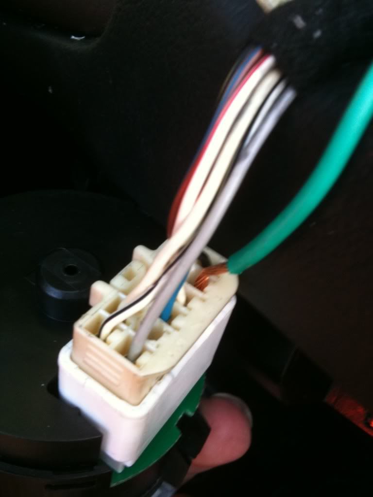
Step 2: Remove harness from back of switch and check that you have a connector that will fit the little connectors on the back of the switch. Once you know it fits see how well it fits inside the plastic harness connector. Mine didnt so i used a 3mm drill to ease out the hole till it fitted.

Step 3: Connect 5A wire to connector and install into plastic holder and then connect to headlight switch. You may need to force the connector on separately depending on what size it is.

This photo shows where in the harness you need to connect it up to. Anywhere else and it wont work.

IMG_0053.jpg


Step 4: Run 5A wire from switch through a grommet in the firewall through to where you are going to install the relay.

Step 5: Run 15A wire from the Positive of the battery. Install 15A spade fuse as close to the battery as possible. Run 15A wire to relay. Before relay splice in the 5A wire and run this to the Relay as well.

Step 6: Connect 15A and 5A wire to relay. Connect 5A wire from headlight switch to the opposite side of the relay as the 5A wire that feeds in. You should be able to see from the little diagram on the back of the relay as to how this should work.

Step 7: Remove front bumper and install foglights

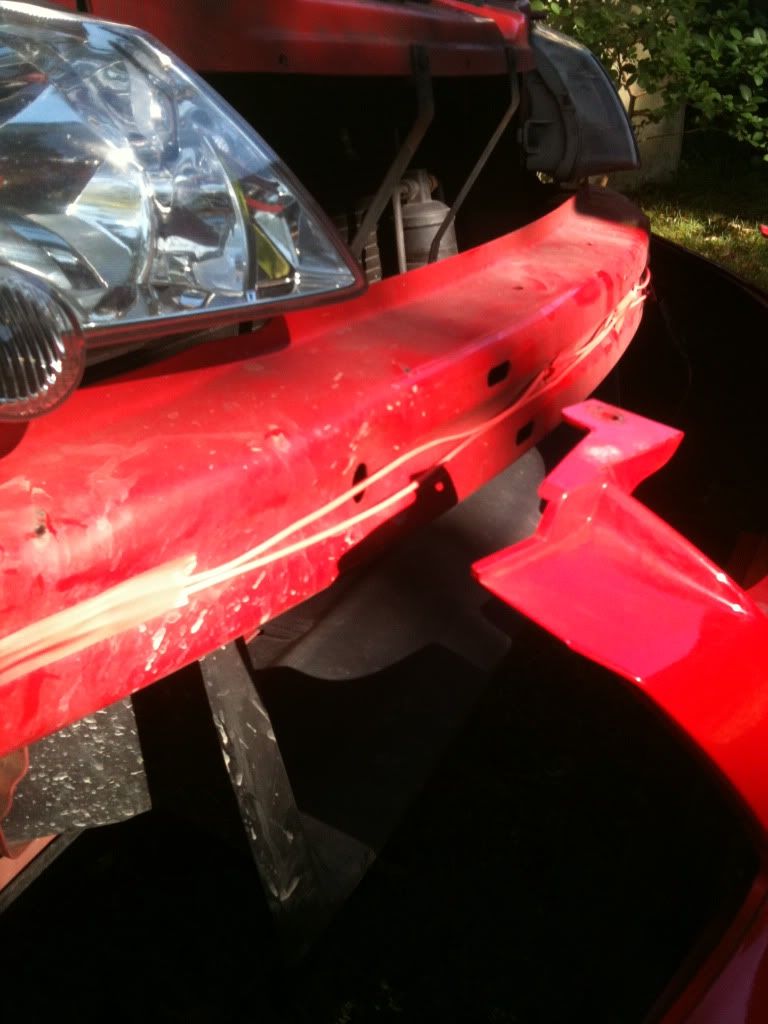
Step 8: Run 2 15A wire down to the foglights. I ran mine down past the horn and then inside the front bumper support to get to the left hand side.

This is how i did it before rewiring. The wires dropped down in front of the radiator and looked terrible but i have rewired it inside the support they are taped to since then to make it neater.

IMG_0057.jpg


Step 9: Connect 15A wires up to male connectors along with a 15A wire of a different colour. Make sure your wires match up (positive to positive, negative to negative) across the connection.

Step 10: Run the negative side of each foglight back up to the negative side of the battery. I think you can earth these wires but its a short distance and also thats how i wired them and never had any issues.

STEP 11: RECONNECT THE BATTERY AND ENSURE THE FOGLIGHTS ARE WORKING BEFORE RE-INSTALLING ANYTHING

Step 12: Re-install headlight switch and front bumper.

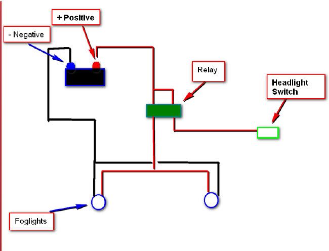
Here's a wiring diagram showing how the circuit should look for it to function properly

foglightswiring.jpg


Any problems i'll do my best to help.

G'day, are you able to upload a picture of the relay you used as my local Holden/anywhere don't seem to know what I'm talking about?
 

Fu Manchu

We’ll get together. Have a few laughs.
Joined
Mar 18, 2006
Messages
18,287
Reaction score
23,184
Points
113
Location
WA.
Members Ride
VZ Crewman, VZ Cross 8, & ya mum.
Looks to be an after market relay going by the numbers quoted.
You'll need to go to a parts shop. (Repco, Bursons, Supercrap)
 
Top